Quad Cannon Test Print

IMG_7370


Just got these polyjet printed and added a single coat of white primer. No sanding yet.

This is the ANH 5′ gun printed at half scale. It was printed in six pieces and includes hollows for 1/16″ steel rods inside the barrels and the articulation points.

I did this as a test print to figure out my tolerances for snap fits and such.

simulator update

I know it’s been a while since I’ve updated the blog – but believe it or not, I’ve been too busy Falconing! Lots of updates to come for sure. Here’s an update to the simulator for the Full Scale project. All sorts of new stuff like: language translation between Aurebesh and English, new onscreen navigation widgets (including a dynamic flightpath) and probably most importantly, an on-screen help text (press ? to access).

I’ve also included they ability to power-up or power down the Falcon (press “I”) – you never know when the empire is listening in…

Screen Shot 2015-02-26 at 1.11.38 PM

more ring work

I started working on the other docking ring finally. It’s just about complete. I have Andre checking my work at the moment and once we think it’s good to go, I’ll post it to my grabCAD page for all.

The port-side was a bit trickier as we didn’t have as good a 3d scan of it, so I had to employ some other photo projection techniques to get the placement of the parting lines correct, but the same basic method was used as for the starboard ring. 3D mapping of the photographs to a 3D model underlay, trace out the grooves then unroll them into a flat pattern, then re-wrap them around the ring as geometry.

I’ll be posting them a few different ways: I’ll post the 3D files of the starboard and port-side rings as shown – with the armor modeled in. And then another version as a blank ring and the 2D files for laser-cutting the plates, if you want to bond the plates on traditionally.

I did re-work the starboard ring a bit once I got into the port-side. I noticed that the area where the SeaLab III struts attach varied a bit from ring to ring. they were inconsistent by a half a degree or two – so I made them consistent. The struts should land perfectly on each of the rings making a nice “X” pattern in profile view from corner-to-corner along the docking arm end-caps.

MF_DockingRings_141029_PS_jm.8 MF_DockingRings_141029_SB_jm.7 MF_DockingRings_141029_PS_jm.6 MF_DockingRings_141029_SB_jm.5

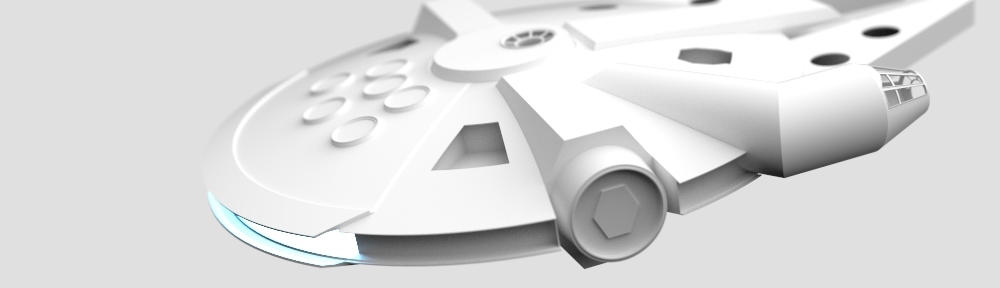
Here they are in context. So small compared to the rest of the model! These are shown on our 5′ base model…

MF_DockingRings_141029_jm.9

docking ring studies

So here’s a fun one!

Got a small section of Andre’s 3D photometric scan of the 5′ Falcon and started using it for the digital reconstruction.

MF_DockingRing.328

We built a generic version of the docking ring…

MF_DockingRing.332

Then I traced the armored plates onto the generic ring using the 3D scan as an underlay to get exact plate lines. The plates were added to the generic model…

MF_DockingRing.331

Next the plates were digitally unrolled from the cone shape to make a flat pattern…


Falcon63_DockingRing_2DProfiles_20140720b

Continue reading

mclaren chasis

MF_McLaren_PartNo2.334
Thank you Andre for supplying the base model for this. I’ll probably be posting versions of the “original” part and of ones that have been modified to fit the falcon dome. Also one with thicker wall section for smaller build (like my 32″ scale).