I never expected to use 3D scan data verbatim. My intent was always to model clean versions of parts optimized for assembly and printing. However, I also didn’t anticipate just how useful the scans would be in unusual cases—like these P-51 Mustang engine parts, which were used with some sprue still intact.
It seems likely that these gates were added to the tooling after the molds were made, once it became clear that knit lines were weakening the parts. The small bridges midway through the sprue improved mold flow, but since they were added by hand, they have a quirky, inconsistent quality. Interestingly, they also became an easy way to distinguish part 31 from part 36—two otherwise nearly identical components.
I bought myself a 3D scanner which should greatly enhance my creation of digital donor kit parts. My digital library has grown to several hundred parts, and this should help with some of the more complicated, or hard to measure bits. Tank hulls are notoriously tricky to get right.
Here is my first scan of a Nitto King Tiger (1/48… or is it 1/50?). A bit soft in the smaller details, but perfect for wayfinding.
This was done without any scanning spray, so I hope to refine my workflow and get slightly better results. The circular scars on some of the flat surfaces are from where I had placed tracking markers.
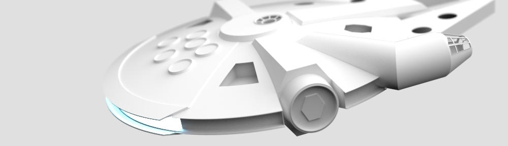
This little collage of parts was used both on the Falcon and Y-wing. It was cast and used to anchor the M8 dozer blades all along the tail section—26 of them on the Falcon in all.
While I obviously love the vehicle designs of Star Wars, there are things about Star Trek that I find fascinating from a design perspective. And then there’s Lower Decks. That one just hit different.
Our family completely fell in love with the Cerritos crew and their ship. It’s both quirky and capable—fitting perfectly into the Star Trek universe while still feeling totally unique.
As Season 5 came to a close, I wanted to honor that crew by building a model of their ship. I up-detailed it ever so slightly to make it feel as real to me as the show did, but not so much that it lost its cartoon charm.
I tried to capture the nuance of the design—like the way they use forced perspective in the nacelles to make it feel faster. I also prefer the detailing on the aft side of the engineering deck from Season 1. And while I get why they removed the two rows of windows across the tail, I felt it looked better with at least some detail in their place.
The actual lower decks are supposed to seem undesirable, but I can’t imagine a better place to be than nestled between the two impulse drives, looking out over the engineering bay with the universe in our wake.
Some details don’t scale well in reality. For example, the escape pods end up being about 75% the size of their Intrepid- and Sovereign-class counterparts when sized to match their on-screen reference. Some of this might be due to the scale change after Season 1—originally, the ship was said to be 794 meters long, but that was later reduced in canon.
This isn’t goodbye—just a farewell for now. We hope to see you again in a future series or a triumphant return to Lower Decks. Godspeed, Cerritos and crew.
The full-scale 535.2 meter model can be found here on GrabCAD.
Between Sean’s build, Stu’s build, various other builds I’ve seen online, and countless images of the naked ILM structure, I’ve had plenty to reference and ruminate about in regards to my own build.
I think I’ve said it plenty of times – the challenge with building a replica is that ILM got to make stuff up as they went. The size and proportions of things were the result of impromptu decisions and ad-libbing. A replica seeks to capture all that nuance (within reason) and is of a known quantity. This tends to be a slower process.
Late last year and over the New Year’s holiday I had a chance to put my ruminating to the test with my first full-sized prototype of an armature. For the final model, I want the armature to be light, strong, and resistant to warping, sagging and environmental effects over time. I will make it out our Carbon Fiber plate. In the short-term however, a plywood version of the armature will tell me a lot about how things fit, its stability, and assembly order.
I had all the parts laser cut from 1/4″ and 1/8″ hobby ply and after a few dry-runs practicing assembling things in sequence, got to clamping and gluing in stages.
As each spar is added to the assembly it gets more and more rigid. Even in relatively flimsy hobby ply, this structure is strong enough to stand on.
We build to learn – and I think for the next iteration, I’ll make a pin-registration table to allow me to align the mandibles in space relative to the saucer. I don’t think my plywood build is off by much, if at all, but knowing is better than not knowing. The rods will be 3/8″ and threaded; which will allow me to create height adjusted platforms to stabilize the z-axis as I go.
There are also a few additional spars I’ll add for some extra torsional rigidity.
I had an old Bogen tripod laying around that I used to prop it up for a walk around. This isn’t the actual mounting configuration – there are provisions for a “knuckle” in the centroid of the model that will receive a model mover rod and mounted on an engine stand for greebling.
The next step is to build the domes (ugh – the domes, the bane of any Falconer). The plywood buck will give me something I can hack-up to test fit domes on since I’ll want my final armature to fit the domes, not the other way around most likely.
it seems every one is playing with A.I. image generation these days. I find the tool to be both fascinating and addicting. Most of what it makes is garbage, but there are occasional gems that simply blow my mind. Most of these rely on the eye of the beholder. The computer dreams. We dream along with it.
midJourney really struggles with specifics like X-wings and TIE fighters. But I’m happy to indulge in this universe too.
Admiral Ackbar enjoys a mealsketch me some space frigatesVader selling his car (of course he drives a Beetle – thanks for making me laugh midJourney)various spacecrafttaxi drones and terminalssci-fi interiors
space ports
Blimps
While the A.I. struggles with Star Wars iconography, I was shocked at how well it could represent a Ford Mustang from the future – blending cues from past and present to make something plausible and exciting.
In April 2015, Andre and I “published” our first drafts of a blueprint for the Falcon. This got the attention of a few fellow Falconers and our little family was born. Sean Sides, Stu Brown, Doug Maio, Andre Bustanoby, and myself would spend the next six years together chatting about all things Falcon. Identifying new donor parts, trying to figure out the proportions of things, etc.
We did most of this on Slack – and some 50,000 messages (mostly “LOL”) and several gigabytes of photos and files later, Sean has a fully realized Falcon, and Stu (by his own best guess) is three-fourths through his.
Millennium Falcon by Sean Sides premiering next to the restored Dykstraflex motion control camera used to film the original Star Wars miniatures.
Sean taught us a lot. He was our trial run. As he built, he let us know where we were wrong (and right). He reworked as much as he could in real-time, but otherwise plowed through as only Sean can, and we rolled as much knowledge into the next rev of CAD in his wake.
Yearly (or more) snapshots of our iterative process
We have a lot of iterations. Stu mentioned he was using version seventeen. That’s mostly true. That’s version 17 of his Falcon model (which currently sits a v22). I keep a digital twin reference model of every team members’ build in case we need to go back and pull a specific dimension or reference. In aggregate we’ve done hundreds of iterations over the six years. And hundreds more if you factor in the progression of the subassemblies – I think our upper gun platform revisions alone were in the upper-fifties before we were happy with them. And then there’s the quad-cannons, docking arms, jaw boxes, docking rings, and on and on.
I thought it would be fun to superimpose all our key milestones. Fusion 360 keeps internal version numbers – but that is every single save – otherwise, we do our own mile-stoning; duplicate the working file, and dump it into an archive to have more discrete checkpoints. Or in some cases the Sean model, or the Stu model, etc…
The X-Wing project really helped Andre and I refine a workflow to truly nail the proportions of a model and the tracking points for reference. Below shows one of a dozen reference images we used for the X-Wing to track points in 3D space, extract them to CAD, and the use them as reference for final surfacing in Alias.
X-Wing digital model and photo composite as seen in X-Wing Part 1.
We’ve been using a similar process on the Falcon all along, but the X-Wing project really allowed us to tune our process, and verify that process against known fuselage dimensions since Jason had original X-Wing parts in-hand. Being able to make hypotheses, and verify that those hypotheses were correct as a scientific control to prove the fundamental method gave us greater confidence in what we’ve been doing with the Falcon. When we re-render our tracked surface data over our Falcon photoset (we have a little over 130 photos that we use for our Falcon 3D tracking) we have pretty tight alignment – original model’s idiosyncrasies not withstanding.
3D surface data reprojected onto photo and rendered. photo credit: Andre Bustanoby
Six years later, we are more confident than ever that what we’re divining is dang close to the original. Onward!
We’ve been working with Stu (and Andre, and Sean, and Doug!) since 2015 on this project. It has been wonderful to see the birthing of another Falcon into the world. If only they were as easy to build as sitting on an egg… We learned so much from Sean’s build, and they just keep getting better. Great work Stu!