For some reason, StudioScale.com is no longer around. It was a great repository for all things Falcon. I managed to grab all their model kit scan images before they disappeared and have reposted them here.
Enjoy.
For some reason, StudioScale.com is no longer around. It was a great repository for all things Falcon. I managed to grab all their model kit scan images before they disappeared and have reposted them here.
Enjoy.

I’ve made available a base model of the main console. It will be a while before a fully detailed version is up, but thought I’d share what I have on GrabCAD.
I am currently rebuilding parts of the Nav Comm chair based on some new information.

I have most of the console proportions roughed-in and some of the buttons and switches starting to populate the dash. Still plenty to do, but with each major chunk I add, I have new insight as to the proportions of the other bits…

Where to begin on these? These particular parts of the cockpit might be even trickier than the Nav-Comm seats. There is almost always someone in them and are typically in shadow. But after countless hours on the internet and consulting some car aficionado friends, I’m pretty sure they are seats out of a mid-70’s Porsche 930 (911 Turbo). But not stock seats of course.
Corbeau is a maker of aftermarket seats for Porsches and made seats in this era and their construction techniques and proportions seem to be very close to what we see in the Falcon. Did they offer them in tan suede with a vinyl back? Probably, but not positive.

So what’s this give me? It establishes a footprint for the seat – they still sell seat mounting brackets for 70’s Porsches. It also gives me a pretty good idea of what the envelope was that the original seat fit into – height, width depth – as aftermarket seats are still available – although changes to seat belt laws and such have changed the designs of modern seats.

The Nav-Comm seats seen directly behind Han and Chewie, are based on Martin-Baker Mk IV ejection seats. Specifically the weight reduced variant found in the English RAF’s Sea Venom FAW.22 – the MB 4AV1-2. It seems to be very rare.
Here’s my current CAD model of the seat. It’s a work in progress since everytime I add something new, I realize how much is wrong with what I’ve build. I think I’ve rebuilt that head-piece about a dozen times.
On the upper left is the ejection seat’s Time Release Mechanism and on the upper right is the Drogue Gun – both of which remained in tact on the Falcon’s seats.
I’m pretty sure the seat back and seat pan pads are from folding chairs and the ribbed sections are 1″ foam rubber (weather stripping) laid in pattern. I think there is also a bit of pipe insulation used around the ejection seat frame. and then there is a lay-up of 1/4″ milky white plexiglas strapped to the back that covers-up most of the catapult tube.


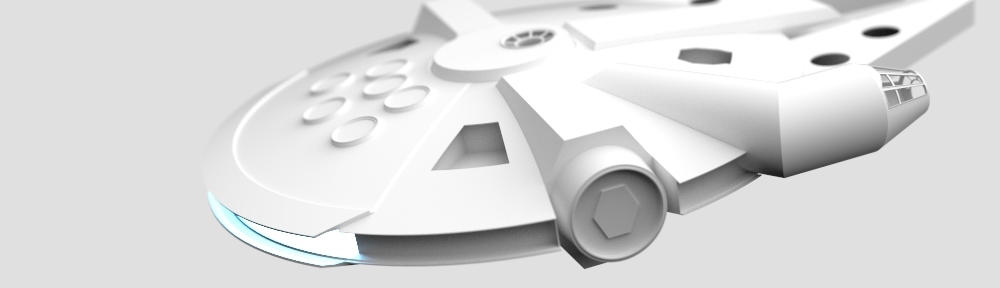
After taking a three-year hiatus to remodel the house and have a baby, I’m back. Of course, things change in three years, I’ve had time to reflect on the project and learn quite a bit.
One of the things that stymied me regarding the falcon build was how I was going to resolve the things I liked about the 5-foot model into my 32″ version. Then I started trying to reconcile the interior (or at least the cockpit, which is the part of the interior that is visible from the outside) and this proved to be real head-mash.
After extensively reviewing footage and photos of the cockpit set piece and this helpful thread on the RPF, I realized that it would be tricky, at best, to find the parts I needed to detail a accurate cockpit at scale using found kit parts. I then decided the best path would just be to replicate the the whole set and then scale the whole thing down to fit my 32″ version and then 3D print the bits needed.
So if it wasn’t enough to endeavor researching all the little bits that go on the outside, I’m learning a whole heck of a lot about what went into the inside.
This approach has meant some changes to my master model – the cockpit cone is now accurate to the set piece rather than either the 32″ or 5 foot versions (except for the very very front window struts – which I prefer to be more parallel than wedge shaped. The main struts are still tapered though).
I moved the whole site away from Apple’s defunct iWeb and is now a WordPress site. Just FYI…
J.

I’ve been rethinking the sub-frame assembly. Originally I had planned on notching the longitudinal and latitudinal extrusions together, but this may have compromised the strength of both.
Lapping them together with L-shaped extrusions top and bottom may be a better solution. This allows the longitudinal and latitudinal assemblies to float independently of one anther until final assembly – allowing me to pick-up any tolerance build-ups I may encounter.

I went to the Seattle Comicon today. I was hoping someone there might have a Master Replica Falcon on display. No such luck – but there were a bunch of Stormtroopers surrounded by latex-clad bunnies. Um, ok…

Today my wife an I took a trip out to one of Seattle’s surrounding islands to visit Keith – the guy with the mill. We enjoyed the sun and ferry ride, and Jenn even put-up with my ‘pew-pew’ noises as we passed buy the container cranes…